 NIRMIO
Electrical project 3: IoT Smart Energy Meter with Real-Time Dashboard
Measure and log the energy use of different household loads and show it live on a phone, with a cost estimate...
View project and guideProjects / Electrical / Electrical project 48
Approx. component budget: Rs. 4,000 - 8,000
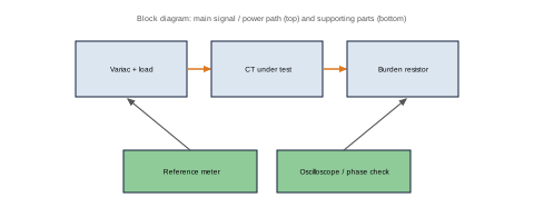
Wind and test current transformers and find their ratio error and phase error at different currents and burdens.
Toroidal CT cores with different turns and burden resistors, a primary current source (variac and heater load), reference meter and an oscilloscope or phase-detection circuit.
How CTs work, accuracy classes and burden, which are fundamental in metering and protection.
Toroidal cores, enamelled wire, oscilloscope, reference meter, Excel. Never open-circuit a CT secondary while the primary carries current, and use an isolated, fused test set-up.
Replace [x] with your own measured results. Write only what you really did.
A short guide that helps you decide and prepare. It contains:
We send the PDF on WhatsApp after your payment is confirmed. Payment details are shared in the chat.
Measure and log the energy use of different household loads and show it live on a phone, with a cost estimate...
View project and guideBuild a digital wattmeter and find its accuracy and error against a reference meter for resistive, inductive a...
View project and guideMeasure earth resistance with the three-point method and see how soil type, moisture, electrode depth and salt...
View project and guide