 NIRMIO
Electrical project 3: IoT Smart Energy Meter with Real-Time Dashboard
Measure and log the energy use of different household loads and show it live on a phone, with a cost estimate...
View project and guideProjects / Electrical / Electrical project 35
Approx. component budget: Rs. 4,000 - 8,000
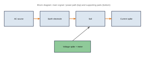
Measure earth resistance with the three-point method and see how soil type, moisture, electrode depth and salt treatment change it.
A low-voltage AC source with an isolating transformer, a current and voltage measurement unit, test electrodes and spikes at set distances, and a model earth pit with different soil mixes.
Earthing design and testing, soil resistivity and the safety reason behind earthing, a common task in electrical inspection and testing.
Isolation transformer, multimeter, copper electrodes, soil samples, Excel. Use low voltage only, and do not run the test near live equipment.
Replace [x] with your own measured results. Write only what you really did.
A short guide that helps you decide and prepare. It contains:
We send the PDF on WhatsApp after your payment is confirmed. Payment details are shared in the chat.
Measure and log the energy use of different household loads and show it live on a phone, with a cost estimate...
View project and guideBuild a digital wattmeter and find its accuracy and error against a reference meter for resistive, inductive a...
View project and guideDetect loose connections and overloaded parts by thermal imaging and set alarm temperature rules for a panel...
View project and guide