 NIRMIO
Electrical project 11: Digital IDMT Overcurrent Relay: Time-Current Characteristics
Build a digital overcurrent relay and check how well its trip times follow the standard IDMT curves for differ...
View project and guideProjects / Electrical / Electrical project 4
Approx. component budget: Rs. 8,000 - 13,000
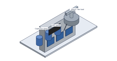
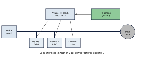
Detect lagging power factor automatically and switch capacitor steps in to bring it close to unity, then measure the effect on line current.
A set of capacitors switched by relays or contactors in steps, a power factor sensing unit with a microcontroller, a display and inductive test loads such as a fan or motor.
Power factor, reactive power and capacitor sizing, used in every industrial electricity system.
Arduino/ESP32, voltage and current sensing, relays, power capacitors (rated for AC), Excel. Discharge capacitors after use and keep all wiring enclosed.
Replace [x] with your own measured results. Write only what you really did.
A short guide that helps you decide and prepare. It contains:
We send the PDF on WhatsApp after your payment is confirmed. Payment details are shared in the chat.
Build a digital overcurrent relay and check how well its trip times follow the standard IDMT curves for differ...
View project and guideBuild a residual current device model and measure its trip current and trip time for different leakage current...
View project and guideSwitch the load between sources automatically in a set priority and measure transfer time and behaviour during...
View project and guide